Showing posts with label GPS. Show all posts

Friday, 13 January 2017

Nearmiss-o-meter, Build Guide, Part 1

Build Guide, Part 1

This part of the build guide uses the PCB design available here on GitHub. It is possible to replicate the circuit design using a pegboard, but I wouldn't recommend it.

The list of parts I have used is available here.


Nib Removal

Clean Up the PCB

When the boards are manufactured, they often have small 'nibs' left on the edges (circled red). Carefully break these off with a small pair of pliers and use a file to remove the remnants.

Click on the picture for an enlarged view.


Sonar Bridging

Solder the Sonar Bridges

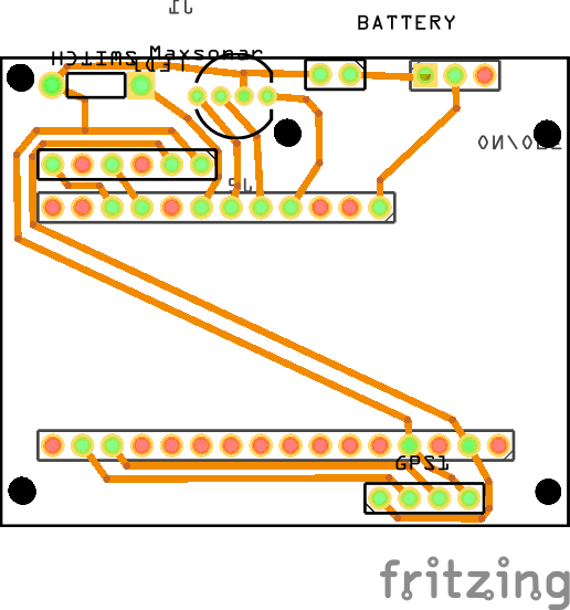
There are two bridging pads on the PCB to allow the use of the US-100 or the MaxSonar (not yet tested).

The photograph shows where I have bridged with a short length of wire for the US-100 sonar.


Cut the Header Pins
Female Header Pins Cut Into Groups

We are using round low profile header pins to install the Feather M0, partially because this is an expensive (and reusable) component, but also because we need to remove the Feather to solder other components onto the PCB.

Using a sharp knife, cut both male and female header pins into five pairs and three singles.


Male Header Pins Before Cutting
- Note Orientation

Solder Header Pins into the Feather M0

Note the male header pins have a top and a bottom. The flat face (shown in the top pair in the photograph) seats against the Feather.


Solder Headers Using
A Breadboard
Use a breadboard to hold the sockets and pins vertically as you solder the pins into the Feather.  Note: the photograph shows extra pins (9 and A0) on my board - these are just remnants of previous incarnations.

Solder pins to: BAT, EN, 11, 10, 6 , 5, 3V, GND, A2, A3, A5, RX and TX.


Solder from bottom of PCB

Solder the Header Sockets onto PCB

With the header sockets still attached to the Feather M0, solder them from the bottom of the PCB.

Once soldered, cut the pins back as tightly as possible, particularly the three nearest to the Sonar, the ones in front of the Molex and the one connected to the BAT pin. It may be better to cut these pins flush with the PCB before soldering -they must protrude no more than 0.5mm.

Header Pins for Feather
Note the Feather will be off centre - this is to allow the SD card to project into the case side wall.

Again, ignore the extra pins on my board!

The top of the PCB should now look like this.


Resistors R1 and R2

Solder LED and LDR Resistors/Jumpers

The LDR (R1) and the blue LED (R2) resistors are soldered onto the bottom of the PCB and the red (R3) and green (R4) resistors are soldered to the top.

I am using a 100KOhm resistor for the LDR and insulated jumpers wires for the LEDs as they are rated for 3.3volts.


Resistors R3 and R4
Make sure the tails of R3 and R4 are cut as flush as possible to the PCB so the Molex socket can sit flat. Once cut off, you can push them back with the soldering iron as there is plenty of space above - or as above, cut them flush before soldering.


Molex Socket and Switch

Solder Molex Socket and Toggle Switch

These are soldered onto the bottom of the PCB. Try to ensure they both sit as flat and square as possible.

Note: Both of these need to be tight to the PCB, but make sure there is plenty of clearance between the toggle switch and the 3V header pin before soldering.


Blue LED

Solder the Blue LED to PCB

This is the (optional) indicator of a near miss - also used to sanity check.

Bend the lens to 90°, ensuring the correct orientation of the positive and negative legs. The positive leg (on the right with the lens facing you) need to be covered with a short length of insulation.

Solder to the PCB and cut any excess short as usual.


GPS Module Headers

Solder GPS Headers

Use the breadboard to solder the headers to the GPS PCB with the uBlox module face down. These are standard square headers that are normally supplied with the GPS module.

Try to keep the PCB as square as possible.


GPS Antennae

Attach the GPS Antennae

A small piece of double sided sticky tape, or a very thin blob of bluetac will hold well enough.

Note the routing of the antennae wire.


GPS Soldered to PCB

Solder the GPS to PCB

Solder the PCB module onto the top of the PCB, again ensuring it is as straight as possible.

Cut the header pins as short as possible, either before or after soldering.


US-100 Sonar Position

Solder the US-100 Sonar to the PCB


The sonar mounts on the underside of the PCB. It should align evenly on each side of the PCB (it is slightly narrower).


Make sure the sonar PCB (green) is no more than ~0.5mm from the main PCB (purple).


Sonar Soldered from Top
Solder the pins shown in the top view here (only four of the five pins need to be soldered).

While soldering, make sure the sonar PCB remains perpendicular and parallel (~0.5mm) to the main PCB. Solder a pin at one end, check alignment, then solder the pin at the opposite end and re-check. Do not solder the remaining two pins until you are sure the alignment is spot on.


Battery Fly lead and LDR Position

Solder the LDR and Battery Fly Lead to PCB

If you have already printed a 'snorkel', use this to position the LDR facing the side of the snorkel, otherwise just leave a small gap between the LDR and the sonar. It is a little difficult to see, but the LDR is no the right hand corner of the PCB in the photo.

The battery fly leads only need to be ~25mm long. Once soldered in, use a hot glue gun (on the PCB/wire junction) to provide some support (not shown in photo).


The next post will detail the switch build.

Tuesday, 10 January 2017

Nearmiss-o-meter, Bill of Materials

Bill of Materials (BoM)

Apologies for the delay since the last nearmiss-o-meter post. Sometimes life throws you higher priorities than the side project you happen to be working on...

These are the items I have used to build a near-miss-o-meter (version 04). Prices are approximate and primarily from UK suppliers. You may be able to buy cheaper directly from China/US.

I have not provided direct links for some suppliers (e.g. eBay) because the items seem to change so rapidly. If you search for the title or quoted description it should return the correct items. Where I've used 'standard' components, I've linked to the the appropriate manufacturer or supplier.

I've tried to brush up on my old photographic knowledge, so a click on the images should provide a higher resolution version.


Adafruit Feather M0

Adafruit Feather M0 Adalogger

This Arduino has an on-board Micro SD card plus Lipo battery charging. See Adafruit website for details. Make sure you are buying the M0, not the 32u4.

The Micro SD card is only used to store the configuration file and the near miss log files. The logs are in CSV format, generating less than 1kB of data per hour, so any standard capacity/speed card you happen to have lying around will likely be enough.

Cost: ~£21.00


uBlox Neo 6M Module

GPS Module uBlox Neo M6

The uBlox Neo 6M GPS module seems to give the right compromise of price, accuracy and reliability. Often listed as an 'Aircraft Flight Controller' for Arduino, there are a couple of different form factors - both work, but only the one with the loose antenna will fit the case properly.

Cost: ~£12.00

The Neo 7M has slightly better 'accuracy' (uses GLONASS) but is more expensive and will need a modified case because the antennae is thicker.


US-100 Serial Sonar

US-100 Ultrasonic Sonar

The US-100 does all the range timing 'on-board' and has temperature compensation too. More reliable, consistent & robust than the ultra-cheap (HC-SR04) sensors.

Cost: ~£7.00

An alternative is the MaxSonar (I have tested the MB1010 EZ1 at ~£20.00, but using outdoors voids the warranty. Weatherproof versions are ~£100). The PCB is designed (but not yet tested) to use either US-100 or MaxSonar via solder jumpers.


Round Pin PCB Headers

Low Profile Round Pin PCB Headers

These are fairly unusual (I could only find them in small quantities from Hong Kong), but allow the Feather board to be mounted 'upside down', making it a similar height to the GPS+antennae.

Usually described as 'Male Female Black 40 PCB Single Row Round Pin 2.54mm Pitch Spacing Header'...

You need both male and female.

Cost: ~£1.00.


Molex Connector

Molex Connectors and Terminals

This is a 4 way/pin right angled socket attached to the PCB and a plug attached to the ribbon cable.

Socket: 70553-0003

Plug: 50-57-9204

Crimp Terminals: 16-02-0086 

I chose these because they are the smallest form factor that still has a 2.54mm pin spacing. The specified plug is a friction type which will help protect the unit if the cable is snagged, but the socket will also take a latching type for extra security if desired.

These are sort of optional as you could solder the ribbon cable directly to the PCB.

Cost: ~£2.00 per set, but may need to order multiples.


Toggle Switch

PCB Toggle Switch SPDT

Used to disable the Adafruit Feather by grounding the ENable pin. This does not isolate the battery (so it can be charged).

This is from RS Components: 734-7220

Manufacturers Part Number: 2MS1T2B4M6QNS

If using the PCB, the pin arrangement needs to match (2.54mm spacing).

Cost: £1.00.


Momentary Switch

PCB Momentary Switch

Used to start/stop recording and for tagging. This is a cheap and dirty switch but we do some 'debouncing' in software to overcome its limitations.

If using the switch case, this will need to be the 1.5mm button version (the lowest available).

Cost: ~20p, but may need to order multiples.


Red, Green and Blue LEDs

3mm LEDs

Three 3mm LEDs are used: Red for GPS status, green for record status and (optionally) blue for near miss indication and sanity check.

I have used cheap 3.3 volt versions from eBay but the light output is not consistent across the colours. The PCB design includes provision for resistors, so a lower forward voltage can be used with the appropriate resistor in place.

If you're using 3.3v LEDs, then you'll need some short lengths of insulated wire to use as jumpers in place of the resistors.

The LEDs for the switch PCB need to have 2.54mm spacing on the legs, and if using the switch case sit no higher than 5.5mm when mounted on a PCB.

If using the blue LED, you'll also need a short piece of insulation (shrink wrap or pulled from a piece of wire) as the legs are quite close to metal parts of the sonar.

Cost: ~20p each, but may need to order multiples.


Light Dependent Resistor

LDR [optional]

An optional Light Dependent Resistor is used to dim the GPS and record LEDs according to ambient light level. You'll also need a resistor.

I implemented this because 'superbright' LEDs are needed for daylight but at night (or when testing) you'll end up with spots before your eyes...

I'm using a 100KΩ (Ohm) resistor with a 70-200KΩ LDR from Maplin.

Cost: ~£1.00


Resistors

You will need three resistors (or jumper wires) to match the red, green and blue LEDs and one for the LDR.

There are several online resources to calculate the resistors required for the LEDs. eg: LED Center or LED Calculator.


Evil Mad Scientist has a bit more in-depth information.

Cost: ~£1.00


Ribbon Cable

This is used to connect the remote switch. I have used ribbon cable but any four core cable will do. If you're planning to use the near-miss-o-meter case with the optional cover, then you'll need to use thin flat cable.

Cost: Free if stripped out of an old PC...


Oshpark PCBs (front and back)

PCBs (or Pegboard and Patience)

All of the components have been chosen for 2.54mm (0.10") spacing on the pins. This is, first and foremost, to allow easier soldering, but it also allows the same circuit to be implemented on both a PCB and a pegboard.

I really cannot recommend a pegboard. It's perfectly doable, but tedious and time consuming if your soldering skills are not ninja level.

Cost: The two PCBs (main board and switch board) are approximately £4.00 per pair (ordered in sets of 3 from Oshpark).

The Eagle .brd files are here on GitHub - just upload them to Oshpark or your favourite PCB manufacturer.


500mAh LiPo Battery

LiPo Battery 500mAh

If using the near-miss-o-meter case, this needs to be a 500 mAh measuring approximately 44mm x 25mm x 9mm.

Cost: ~£3.00 each (ordered as a set of 5 with a charging fly lead)

The Adafruit Feather M0 can also be powered from the USB port, but it would be a shame to not use the onboard charging...


Walkerman and JST Fly Leads

Battery Fly Lead

The battery connector on the Adafruit Feather is a 'standard' JST. Most easily available LiPo batteries have a different (Walkerman) connector. You have a number of options:

  1. Use a male Walkerman fly lead (on left in picture above). There are various vendors who sell 5 LiPo batteries with a charging fly lead... This is the route I took.
  2. Swap the female Walkerman connector for a JST connector and connect directly to the Faeather board. This was the first route I took, but BE WARNED! There is no standard for the positive and negative terminals. The leads I obtained (on the right) were opposite the the implementation by Adafruit (centre in photo), so I managed to fry my charging circuit. I notice Adafruit now have a warning notice on their site...
  3. Solder the battery leads directly to the PCB. Not my favourite option as I like the idea of being able to quickly isolate the battery should the need arise.


Case

I've created a case suitable for 3D printing. The parts are on github here. If you don't have a 3D printer (why not?), they can be printed via 3DHubs - just upload the files choose 'PLA' material and search for a suitable printer (often quite local).

You'll also need two 40mm M3 screws and nuts to hold the base and lid together.

The 'case04-cover.stl' is optional - intended to keep the SD card and USB slots clean and a little dryer if it rains (Although I have used this case in the rain, it is not waterproof in any way shape or form. Use at your own risk!)

Cost: ~£12.00


Handlebar Mount

The case has a GoPro mount on the top, so any mount should fit. Search for 'Camera Handlebar Seatpost Clamp Roll Bar Mount for GoPro Hero' and you should find one like this. Be warned: They are useless for cameras (too much wobble).

If you don't already own a GoPro, you'll also have to buy a 'GoPro long thumbscrew' separately to attach it to the mount.

Cost: ~£4.00

Next up: The Build

I have photographed the build and am currently writing it up...


Wednesday, 11 May 2016

Nearmiss-o-meter, The Difficult Second Album

It's been a little while since the last update. Who'd have thought product development could take so long?

Snorkel Design

The original design.
I've been chasing down a few minor frustrations with the first complete version of the Nearmiss-o-meter.

The first was caused by the design of the snorkel, causing a resonance similar to blowing across the top of a bottle. This in turn 'blinded' the sonar in gusty conditions.

A redesign for the original box, similar to the original cardboard concept resolved this and I have now also redesigned the case to allow interchangeable snorkels of different lengths.

Only measures 6cm...?
It works...
However, a very minor change to the snorkel throat for the new box introduced an echo that meant the sonar read only 6cm!

Spot the difference.


GPS Checksum Errors

The second major issue was a little harder to track down. Periodically, the GPS appeared to stop reporting. A bit of debugging later, and this was tracked down to TinyGPS complaining about an invalid checksum. Most GPS devices (such as the uBlox) send out information as NMEA sentences, which includes a checksum at the end. Both the uBlox and the TinyGPS library are very mature and when I ran them in isolate test, I could not replicate the error. So the bug was very likely in my implementation.

Intermittent issues are always tricky. The key to squashing any software bug is to be able to replicate it reliably, but the the GPS lockups seemed to be random. It would track perfectly for long periods, then stop for 20 seconds, then continue normally, stop, continue etc. Very frustrating.

After eliminating any issues with my code, I started thinking about timing and buffers. The uBlox delivers all the NMEA sentences in one burst. These sentences are only a single line, each of less that 80 characters, but they are all delivered at once, on the epoch of each second (i.e. 1Hz) That's not a lot of data to consume for your average PC, but the Arduino has a default serial buffer of just 64 bytes.

The initial fix was to reduced the number of NMEA messages to just the bare minimum and counter intuitively use a slower baud rate. This seemed to help, but did not solve the problem completely. If the Arduino 'loop' strayed out of sync (i.e. was not ready to read the buffer at the epoch) then the serial buffer would overflow and TinyGPS would not have a valid checksum.

The next step was to investigate increasing the serial buffer. I wanted to avoid this as it cannot be done in the sketch and is different for every type of board, which complicates other peoples setup but it had to be done.

Board Upgrade

In the process of trying to debug all this, I switched from the 32u4 version of the Adafruit Feather moving up to the M0 - a whole 256Kb! The 32Kb limit (actually 28Kb of code)meant I was spending much of my time reducing the size of the code rather than building the functionality I wanted. The Feather M0 is physically identical (thank you Adafruit) but quite different to code for. Most Arduino libraries will run fine but crucially, not the SoftwareSerial. Oh Pooh, said Piglet. We need that for the sonar. Don't worry said Lady Ada, use SERCOM! If you really want to get down & dirty, read this excellent tutorial on muxing and serial SERCOM. I cannot praise Adafruit enough for their documentation.

Serial Sonar Modulation

Moving swiftly on, I then needed to address the serial sonar library. If no object was detected within 8 metres, the sonar firmware would take almost a 10th of a second to respond to a single 'ping'. This is not good when you're attempting to read the median of five pings, five times a second. No amount of messaging would persuade it to abort mid ping, so I have implemented a 'modulating' median ping. The library will do as many reads as it can (up to 5) within a given time frame and then return the median. Sorted.

New stuff

Moving to the M0 allowed me to build in the following functionality:

  • Greater 'accuracy' for lon/lat recording using the TinyGPS++ library. See this excellent reply for further information. We are now recording 6 decimal places - this does not mean the lon/lat will be accurate to 11cm, but is does mean the trace will be smoother.
  • A config.txt file on the SD card to allow end users to change the Nearmiss-o-meter behaviour without having to recompile and reload to the Arduino. e.g. sonar offset, timezone etc.
  • Date/time stamps for files. It didn't bother me too much, but seemed very peculiar to see files dated 01-01-1970... We are still limited to 8.3 file names, but the config.txt above allows both the filename and the timestamp to be in local time rather than GMT.

Disable vs Isolate

For the first version, I simply isolated the battery with a switch. This is the 'better safe than sorry' approach, but it means you would have to switch on the nearmiss-o-meter in order to charge it. Not very user friendly. Adafruit have implemented an unintuitively named ENable pin. If this pin is grounded (it is held high internally), the 3v3 regulator is disabled thereby shutting down the processor and the peripherals. A bit of measuring of the 'quiescent current' with a friends highly sensitive meter and a bit of maths told us the battery would last more than a month in standby mode. I am still chasing down an oddity whereby I can read 0.8 volts between 3v3 and GND when in disable mode...

Other stuff

I've also created a small handlebar button comprising three components (and took a surprising amount of time to design...). This makes it much easier to start/stop recording and 'tag' near misses.

This now has just two LED (red for GPS and green for recording) as the multiple colours did not aid readability. The blue nearmiss/testing LED has moved to shine out of the snorkel along with the light sensor to auto dim the LEDs.

So it is still a work in progress... I hope to have a PCB design ready to send off soon & then perhaps make a couple of boxes for interested parties/patrons to test :-)

Update #1

The Arduino code & Eagle (Gerber) files etc will be published on Github.

The logic behind creating a couple of test units is to ensure other people don't waste their time/money/efforts on something that doesn't work as expected. An example of this is the use of various pins on the Arduino - I've learnt that some can do PWM (for dimming LEDs), others can not. The same for the SERCOM pins.

The second reason for the test units is to prove the usability of the design (developers of software and or physical products are the last people you should choose to do testing) and also to start to understand how the data can be collected/collated/validated etc.


Tuesday, 8 March 2016

Near-miss-o-meter, Arduino Code


A short post to describe the functionality implemented in the initial release of the Arduino software on github. This is the first Arduino/C code I have written, so feedback is more than welcome. It is has been an interesting challenge to get all the things I'd wanted into just 28kB of space. Avoiding the use of floating point numbers in TinyGPS meant I had to take on sprintf (and I won, albeit at 2am!).

The code is structured to allow for easy adaptation to other boards and sonars, so tends to use 'global' variables more than usual. The initial version, built for the Adafruit Feather 32u4 Adalogger, will support 'pulse output' sonars via NewPing and serial output sonars via SerialPing (my first Arduino library, be kind).

The choice of sonars is slightly limited by the Feather running at 3.3 volts, so the ultra-cheap ones such as the HC-SR04 will require either a voltage booster or a 5 volt board. The cheaper serial sonars will run at 3.3 volts.

User interface

The nearmiss-o-meter has an extremely simple user interface, consisting of  three LEDs:
  • Red LED: GPS and battery status.
  • Green LED: Record and tagging status
  • Blue LED: Nearmiss and 'test mode' status
and one push button (momentary) switch:
  • Medium press: Start/stop recording
  • Short press: Start stop tagging (if recording)
  • Long press: Start/stop test mode (will ping sonar without a GPS fix)

What does it do?


Power Up

When the Arduino is powered on, the green LED will flash twice if the SD card is present. The red LED will remain fully lit until a GPS fix is obtained, at which point it will show one short flash per second.

Start/Stop Recording

A medium press on the switch (greater than half a second) will start recording if there is a GPS fix. The green LED will light fully when you have pressed for long enough and when released will show one short flash per second to indicate recording.

Recording is stopped in the same way (even without a GPS fix).

Files are recorded in the root directory of the SD card named in the format YYMMDDHH.csv. Note: the standard Arduino SD library does not support file timestamps so all files will appear to be created on 01/01/1970.

The CSV record consists of:
  1. Date/time in ISO ISO 8601 format (UTC)
  2. Longitude, to 4 decimal places
  3. Latitude, to 4 decimal places
  4. Speed, in kph
  5. Course or heading, in whole degrees
  6. Passing distance, minus offset (if specified)
  7. Tag state, either 0 or 1

Tagging

When recording, the nearmiss-on-meter will log a continuous trace, so the design also allows for continuous tagging (perhaps to denote sections of cycletrack). The switch implements a 'press to toggle tagging' rather than 'press and hold to tag'.

A short press (less than half a second) will start or stop tagging.

The green LED will show two short flashes per second while tagging.

Test Mode

A long press (greater than 5 seconds) will enter/exit test mode, irrespective of whether a GPS fix has been obtained. The CSV data will be sent to the serial monitor (via USB) of the Arduino IDE.

Source Code

The initial release of the source code is here. It is fairly well documented, with links to all the required libraries. Instructions for setting up and using the Arduino IDE are here. 

Have fun!

Part 5: The Difficult Second Album

Wednesday, 24 February 2016

The Near-miss-o-meter, Part 3

From Breadboard to Pegboard

A slightly longer delay from the last post than planned. Partially due to my slow wordsmithing, but primarily due to the distraction of writing smart phone version as a 'cheap-as-chips' nearmiss-o-meter. More on that later.

Rendering in the most compact form.
This post will document the build of the standalone Arduino prototype. This could be packaged either on a custom PCB or home brewed onto a peg board within ~50mm x ~50mm x ~40mm cube (including battery).

The test version I have created is single sided (for ease of wiring), has 8mm high sockets (to enable me to re-use the components) and still only measures 50mm x 70mm x 45mm. It also includes a 3.5mm mono headphone socket for a remote switch.

Please note: All the information here is for guidance only. If you're unsure of what you're doing, please get someone qualified to help (i.e. not me!). Most of the components are fairly benign (although if you accidentally connect a 3.3 volt LED to the 5v USB input, it'll blow the top off and hit you on the forehead...), but the battery stores a lot of energy and must be treated with utmost respect.

Remember, electronic components run on magic smoke - when the smoke is released, they won't work.

The list of components is as follows:
  1. Adafruit Feather 32u4 Data Logger [>]
  2. Ublox NEO-7M GPS [>]
  3. Maxbotis Maxsonar [>]
  4. SPDT PCB Slide Switch [>]
  5. SPST Push Button Momentary PCB switch. [>]
  6. RGB LED 3.3v [>]
  7. 500mAh LiPo battery (optional) [>]
  8. 50mm x 70mm Double sided prototype board [>]
  9. 3.5mm Mono headphone socket (optional) [>]
  10. Square pin header sockets (optional) [>]
  11. JST connector(s) (optional, but the one on the battery will be wrong) [>]
The links to eBay listings are not necessarily recommendations (I'm not a great eBayer...), they were simply chosen as UK based suppliers. The links may also have expired! If you are willing to buy direct (usually from China), prices could be significantly lower. That said, I have had excellent service from all the vendors - some have been above and beyond expectations. If there is enough interest, I may try to put a 'kit of parts' together with one of the vendors.

The headers (10) and the JST connectors (11) can be omitted if you're brave enough to solder the components directly to the peg board. The LiPo battery is optional if you're happy to power via the USB with a phone charger battery.

You will also need to beg, steal or borrow a soldering iron with a very small tip, a small amount of 0.2mm2 solid core insulated wire and a blob of Blu-Tack to stop the GPS module wobbling (it should really be screwed down).

This is quite a lot more expensive than planned, so since building this, I have acquired a few more ultrasonic rangefinders (and one infra-red one) for testing. All of them are much cheaper than the Maxbotix one and two of them have built in temperature compensation in serial mode, so may be better suited. The limitation is the Adafruit Feather board runs at 3v3, which rules out the 99p HC-SR04. I will write a sonar/board comparison post(s) as soon as time allows.

3D Modelling

Rendering with header sockets and pegboard.
To model the interaction of the components, I used a brilliant open source modelling tool called OpenSCAD.

Even (especially?) if you have never used a 3D program before and have the merest hint of programming or scripting knowledge, give OpenSCAD a try. I have created 3d models of each of the components which I will also upload to Github.

The picture to the right shows my double-sided modelling but as it was my first attempt, I swapped to single sided as I started to solder up. I later learnt you're supposed to do all the wiring on the opposite side to the components. It would probably be neater than my efforts. The PCB image from the previous post shows how to wire it up if you're so inclined.

This is the end result. All I need now is a box, a way of mounting it and the remote switch.


Coding for Arduino

The open source/Free software & hardware community really is a gift that keeps on giving. Without all the contributions of so many, this project would not have been possible.

Not only are the specifications of the Arduino hardware open source (which is why you can buy such cheap clones), the IDE (Integrated Development Environment) used to program the Arduino is also freely downloadable. It ships with a *huge* number of example 'sketches' - each and every new library has examples included.

'Proper' embedded programming is new to me. Although I do some embedded Linux, my bread & butter has been enterprise scale databases.  This was going to be a whole new experience. From terabytes to less than 32Kb. Oh my!

Here's the Arduino coding 101: There are just two main parts to an Arduino sketch - the setup() function, which runs once when you power on and the loop() function which runs over and over again until you power off or make the code barf (even then it seems to detect this and restart itself). This makes simple stuff really simple. You want to flash an LED? OK, turn it on, delay 1 second, turn it off, delay 1 second, rinse & repeat:

// From the Blink example:
void loop() {
  digitalWrite(13, HIGH);   // turn the LED on (HIGH is the voltage level)
  delay(1000);              // wait for a second
  digitalWrite(13, LOW);    // turn the LED off by making the voltage LOW
  delay(1000);              // wait for a second
}


Great. Or not so great. While you're delay()-ing, nothing else happens. If your GPS is reporting a position change, you're not going to see it, if your want to ping the sonar - it's not going to happen.

A 'normal' computer handles all of this behind the scenes. As a programmer, if you want a process to not interrupt your user interface, you spawn it off into a different 'thread' that runs in the background - the operating system then 'schedules' all the threads for you. If you're really scaling, you can spawn it off to a whole new datacentre... Not on the Arduino. You have one loop.

Building a simple state machine

Vanilla Arduinos do not do threads (although guess what, there is a library or two for that!), but it does have a number of internal timers. You can obtain the number of milliseconds (or microseconds) since your program started. If you now define how frequently you'd like to turn the LED on or off, you can count the number of milliseconds that have passed then take an action. But while you're counting, you can do other things.

//Pseudo code
void loop() {
  now = millis(); //Get the number of milliseconds since program start
  if (now - previousOnOff >= 1000) { // If one second has passed

    if (ledState == LED_OFF) { // If the LED is OFF...
      digitalWrite(13, HIGH);  // then turn it ON
      ledState = LED_ON;       // and record the state
    }
    if (ledState == LED_ON) { // If the LED is ON...
      digitalWrite(13, LOW);  // then turn it OFF
      ledState = LED_OFF;     // and record the state
    }
    previousOnOff = now; //Save the time we last turned the LED on or off
  }

  //Here we can do other things
  //. . .
  //And even more things 
  //. . .
}

There is a surprising amount of functionality required that has to fit into just over 28kB. Looking through the code now, I have implemented the following:

GPS Read

Using the TinyGPS library, the location is read via serial, once per second. This is the default transmit rate for most GPS modules. The rate can be changed but the setup codes appear to be different for each version, so it went in the 'too hard' pile. Once per second works well, but the code is designed to cope with faster or slower updates.

From the GPS data, in addition to longitude, latitude, heading and speed, we also get the (very precise) time, which we use for both logging and to create the name of the log file.

When we do not have a fix, the raw NMEA data is sent to the USB serial port for debugging. The red LED will remain lit until a fix is found (or subsequently lost), then flashes once per second.

Sonar Ping

With a little empirical research, I settled on a 'sonar heartbeat' of once every 200 milliseconds. This ensures even fast passes are caught but gives sufficient time for other functions to happen. Each 'ping' is derived from the median of 5 rapid pings to remove outliers, handled by the NewPing library. I have also written my first Arduino library for the two serial sonars which is partially API compatible with NewPing. This means it will only require changes to a couple of lines of code to switch between different sonar modules.

If a near miss occurs (less than one metre), the blue LED will flash rapidly until we have 5 clear pings. This also gives an indication if the sonar is blocked or has barfed and can be used to check calibration.

Write to SD Card

Arduino has two libraries to support SD cards (SPI and SD) which take care of most of the heavy lifting. One minor limitation is the 8.3 file name format (MSDOS is still biting us on the bum), so I settled for YYMMDDHH.csv. If a file already exists, it will be appended. The data is written after each ping but only flushed once every two seconds to reduce battery consumption.

On startup, the presence of the SD card is checked and the green LED flashed twice to confirm. When recording there will be one short flash per second. If a file open or write error occurs, then there will be two long flashes per second.

Flashing the LEDs

To provide an easier interpretation of status, I've used a RGB LED. I've implemented a design that splits each second into 8 segments allowing each state to be indicated by each LED without clashing. The patterns are easy to update and 'visual' in the code:

const byte GPS_NO_FIX    = B11111111; // Continuous
const byte GPS_HAVE_FIX  = B00000100; // Once per second
const byte RECORD_ERROR  = B11101110; // Long flash, twice per second
const byte RECORDING     = B00000001; // Once per second
const byte TAGGING       = B00010000; // Twice per second (in combination with RECORDING
const byte NEAR_MISS     = B10101010; // Four times per second
const byte LOW_BATTERY   = B01010101; // Four times per second OR'd with GPS_HAVE_FIX


These constants also serve as status values, saving a few essential bytes.

Single switch control

The push button implements a medium press for record on/off and a short press for tagging on/off. It could also implement a long press if required. A side effect of the implementation also deals with the 'debouncing' of the switch contacts. No, I'd never heard of it either!

Battery State

This small but essential indicator was the final piece that I was able to squeeze in. On compile I now get the message:

Sketch uses 28,096 bytes (97%) of program storage space. Maximum is 28,672 bytes.

It has taken some effort to trim the code to fit - so although quite functional, it is currently in need of a bit of tidying...

Next Steps

I'm currently learning/working on an Android OTG version, which will significantly reduce the cost of the primary parts. The phone will provide the GPS, logging and power, with the slight downside of a cable connection. Logging to the phone should also enable easier uploads of the data and may provide a basis for a Bluetooth version. However, this is incredibly distracting (read: time consuming) so have not yet started the Github learning curve...

Part 4: The Arduino Code

Thursday, 4 February 2016

The Near-miss-o-meter, Part 2

This post documents the route I took to arrive at the current configuration of the nearmiss-meter, so you don't have to.

The Digispark in my previous post introduced me to the Arduino family, but with only 8kB of memory it was never likely to have the capacity to process both GPS and sonar data and write it to an SD card. Arduino is not a technology I had played with before starting this project but turns out it is really easy to set up and get going. The 'Blink' sketch is the Arduino equivalent of the ubiquitous 'Hello World' of every programming language ever invented - one of many, many examples that come with the freely downloadable IDE.
En route to the Pantomime on Christmas Eve, we detoured via Maplin picked up an Arduino/Genuino Micro. This comes with a heady 32kB rather than the 8KB of the Digispark.
Adruino Micro, HC-SR04, USB GPS & SD card
Once the festivities subsided a little, I pulled together my collection of components and realised I couldn't just plug the USB GPS into the Arduino. I also couldn't justify (or wait for) a PCB GPS so after a glass or two of brain lubrication I started to cobble together a Python script to read the GPS via my PC USB port, spit it out of another USB port to the Arduino and also read back from the Ardino... Easy peasy eh?

It turns out Python blocks when it reads/writes to/from a serial port so I had to lean about Python threading. Then I had to learn about how you can Ctrl-C from a Python thread so I didn't have to keep manually killing the process! (As an aside, I also learnt enough Python to control my half price Maplin 433MHz remote sockets from my Pi. I'm easily entertained...)

There are a huge number of libraries for Arduino, so the chances are, if you want to do something, someone has probably done it already (and than made a library out of it). NewPing was the first library I 'discovered', when I setup the Digispark. This library does all the complicated stuff for ultrasonic sensors so I don't have to.

Next up was TinyGps, a small but perfectly formed library for parsing NMEA [pdf] data (this is a standard set of strings or 'sentences' that most GPS devices spit out). The sensor built by Dr Ian Walker used a combined Real Time Clock (RTC) and data logging shield. Microcontrollers (and the Raspberry Pi) do not have a RTC so do not know or store the current date and time. The Pi often gets its time from ntp when it boots up, but this requires a network connection. With a GPS we can get the exact time - down to the nano second!

By default, most GPS devices output location data once per second. It is possible to reconfigure the frequency, but the setup strings are not standardised across devices so I've left this alone for now. We definitely want more frequent readings from the sonar and after a little trial and error, I settled on a 'sonar heartbeat' of five times a second. This should not swamp the SD card and will also give sufficient time to get a median reading from multiple 'pings'.

Meanwhile, an SD card board had arrived, so I gingerly plugged it in. The repeated dire warning in many of the pieces of documentation I'd read about SD cards was: "Don't use 5v, anything more than 3v3 will fry your card.". The board I'd bought was listed as running on 3 or 5v, but I suspect I'd not be the first person who bought something from eBay that wasn't quite as described...

I tested with some old/broken SD cards and when they didn't smoke I put in the one and only spare I had. The example scripts for Arduino are brilliant.

I now had a working prototype, albeit with a laptop attached, so I stood at the side of the road and tested of the rudimentary setup. Thoughts turned to power supplies and charging - this Arduino Micro is 5v, so to power it on the move I would need either a portable USB charger or a LiPo battery + a step-up booster + a charging circuit. More components, more complexity. The USB battery is definitely an option when I revisit the Pi version, but for ease of shareing, the unit really needed to be self-contained. Enter the Adafruit Feather  Adalogger.

This featherweight microprocessor had an on board SD card and built-in battery charging. The only downside was it ran at 3.3 volts whilst the cheap HC-SR04 sonars run at 5v. However, it removed the need for several components with just the step up booster required.

With a new breadboard circuit made up, including the newly arrived Ubox GPS board, I now had my first fully portable system. Two resistors gave me the step down for the returned echo from 5v to 3v3.

I'd also ordered a couple more cheap sonars - I wanted to see how consistent their measuring was, but I couldn't get the two new ones to work. It seems not all HC-SR04s are created equal. Some will trigger with 3v3, others absolutely require 5v. Not happy. This would mean having a logic level shifter (new to me too!) - yet another component.

On the plus side, the Adafruit Feather performed well, despite only running at 8MHz but it was time to bite the bullet and buy a more expensive sonar that ran at 3v3. This is the Maxsonar MB1010, from Maxbotix. They have a huge range of sonars for every application, but my choice was based on price and easy availability in the UK as well as noting Ian Walkers use and comments. The top end fully waterproof models are way out of the target price range for this project, but may appeal to some who want to log data in all weather.

A couple of (late) nights later, with the great Antoine de Saint Exupéry sitting on my shoulder, I had reduced the design to the minimum: a single sided PCB with just three main components. Although this design is operational on a breadboard, this PCB layout is currently untested as my local PCB fabricator wanted to charge me £800 'consultation' fee before looking at it! The next step is to implement this on a peg board, to improve the connection reloability of the prototype, then I'll probably use Fritzing to get a test board made up.

Other than the plethora of new new things I've learnt, one of the biggest personal benefits of this project was that for almost the whole of the Christmas and New Year period I watched very little television but we're back into the swing of work/life, time is a little more limited.

I now have the Arduino code mostly written and a rudimentary Leaflet based web 'viewer' of the data.

This is a local street on the way back from my local bike shop that is absolutely awful to cycle along. The colour grading of the line shows red for less than 1m and shades from red to yellow to green for 1m to 2m passing distances. The data is only ever held locally (using Javascript FileReader), so privacy is ensured.

The next post will document the device I have prototyped in greater detail, along with the functionality implemented in the Arduino code. I have created a Github repository, but that is another learning curve I need to overcome before I populate it.


Part 3: Breadboard to Pegboard


Thursday, 14 January 2016

The Near-miss-o-meter, Part 1

It all started with this tweet from @beztweets:
with a link to this great post by Dr. Ian Walker. I'd seen a few of these previously (whenever a '3 foot rule' is introduced somewhere) but the suggested addition of a GPS seemed to make sense, possibly for the Near Miss Project run annually by Dr. Rachael Aldred and Emily Brooke.

Coincidentally, I was about to receive my Raspberry Pi Zero on the front of the MagPi magazine. It seemed like a perfect match: a few days off for Christmas, a £4.00 computer, a £10.49 USB GPS (you can get them cheaper if you're will ing to wait for shipping from China) and a £1.61 ultrasonic sonar (HC-SR04) from that auction site.

The Aim

To create and document a compact design that can be built by anyone using easily available components without requiring a huge amount of technical knowledge. Although I played a little with electronics as a teenager, my knowledge is pretty much limited to knowing the difference between a capacitor and a resistor. I do like a challenge.

This is the first of several posts that will briefly document the journey and finish up with a more detailed 'howto' of a reference design.

Prototype 1: Pi, USB GPS, Sonar


After a mad run up to Christmas, I had half a day free, so started playing. Hooking up the Pi to a breadboard and wiring in the sonar is well documented on the web (e.g. here). Major lesson learnt here was how to drop 5 volts (from the HC-SR04) down to 3.3 volts (also known as 3V3, the maximum voltage allowed by the input pins on the Pi) using two resistors (or any three resistors of the same value using two in series).

With the USB GPS plugged into a powered hub, we were away!

Not quite. The Pi works very well with the sonar as long as that is all it is doing. The HC-SR04 works by setting the ECHO pin 'high' for the length of time it takes for the ultrasound 'ping' to bounce to and from its target, but if you start to add any logic into the measuring process, the Pi wanders off to do other things and forgets to listen to the ECHO pin for a few nano seconds. This results in frequent over-long distance measurements.

Thankfully, I'd done a bit of reading, so it was quickly on to:

Prototype 2: Pi, USB GPS, Digispark+Sonar


A Digispark? No, I hadn't heard of them either. They are a tiny, USB powered Arduino. About the size of a postage stamp and costing all of £2.99 on eBay. Unlike the Pi, this is a realtime microprocessor (with 8kb of memory!).

Shamefully, I'd not yet played with an Arduino before so there was a small learning curve to get up to speed. This excellent post, meant the Digispark was quickly wired to the sonar and plugged into the Pi.

Digispark + HC-SR04
Success! Consistent distance readings now being recorded with lon/lat, time, heading and speed from the GPS. Here we have a complete (hardware) solution for less than £20 (plus a USB booster battery to power the Pi on the go).

There was one minor issue: all the data was being recorded onto the Pi's SD card. This is fine for me (we have been 100% Microsoft free since 1997...) but a Windows PC cannot read the Linux Ext4 file system on the card without installing additional software. It is theoretically possible to dual partition the SD card, but Windows still struggles if it doesn't recognise the first partition. I still think this approach has mileage (particularly overlaying data on video etc) but given my my goal of this solution to be easily built by anyone, this was getting a little too techie. Besides, I was now learning about Arduino - perhaps I should follow Ian Walkers lead...

As you may have noticed from the picture above, I also discovered a new tool whilst trying to document my wiring: Fritzing - the open source world never ceases to amaze me!

Coming up in Part 2: The Arduino(s)