Build Guide, Part 1
This part of the build guide uses the PCB design available here on GitHub. It is possible to replicate the circuit design using a pegboard, but I wouldn't recommend it.The list of parts I have used is available here.
 |
| Nib Removal |
Clean Up the PCB
When the boards are manufactured, they often have small 'nibs' left on the edges (circled red). Carefully break these off with a small pair of pliers and use a file to remove the remnants.Click on the picture for an enlarged view.
 |
| Sonar Bridging |
Solder the Sonar Bridges
There are two bridging pads on the PCB to allow the use of the US-100 or the MaxSonar (not yet tested).The photograph shows where I have bridged with a short length of wire for the US-100 sonar.
Cut the Header Pins
 |
| Female Header Pins Cut Into Groups |
Using a sharp knife, cut both male and female header pins into five pairs and three singles.
 |
| Male Header Pins Before Cutting - Note Orientation |
Solder Header Pins into the Feather M0
Note the male header pins have a top and a bottom. The flat face (shown in the top pair in the photograph) seats against the Feather. |
| Solder Headers Using A Breadboard |
Solder pins to: BAT, EN, 11, 10, 6 , 5, 3V, GND, A2, A3, A5, RX and TX.
 | |
| Solder from bottom of PCB |
Solder the Header Sockets onto PCB
With the header sockets still attached to the Feather M0, solder them from the bottom of the PCB.Once soldered, cut the pins back as tightly as possible, particularly the three nearest to the Sonar, the ones in front of the Molex and the one connected to the BAT pin. It may be better to cut these pins flush with the PCB before soldering -they must protrude no more than 0.5mm.
 |
| Header Pins for Feather |
Again, ignore the extra pins on my board!
The top of the PCB should now look like this.
 | |
| Resistors R1 and R2 |
Solder LED and LDR Resistors/Jumpers
The LDR (R1) and the blue LED (R2) resistors are soldered onto the bottom of the PCB and the red (R3) and green (R4) resistors are soldered to the top.I am using a 100KOhm resistor for the LDR and insulated jumpers wires for the LEDs as they are rated for 3.3volts.
 |
| Resistors R3 and R4 |
 |
| Molex Socket and Switch |
Solder Molex Socket and Toggle Switch
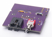
These are soldered onto the bottom of the PCB. Try to ensure they both sit as flat and square as possible.Note: Both of these need to be tight to the PCB, but make sure there is plenty of clearance between the toggle switch and the 3V header pin before soldering.
 |
| Blue LED |
Solder the Blue LED to PCB
This is the (optional) indicator of a near miss - also used to sanity check.Bend the lens to 90°, ensuring the correct orientation of the positive and negative legs. The positive leg (on the right with the lens facing you) need to be covered with a short length of insulation.
Solder to the PCB and cut any excess short as usual.
 |
| GPS Module Headers |
Solder GPS Headers
Use the breadboard to solder the headers to the GPS PCB with the uBlox module face down. These are standard square headers that are normally supplied with the GPS module.Try to keep the PCB as square as possible.
 |
| GPS Antennae |
Attach the GPS Antennae
A small piece of double sided sticky tape, or a very thin blob of bluetac will hold well enough.Note the routing of the antennae wire.
 |
| GPS Soldered to PCB |
Solder the GPS to PCB
Solder the PCB module onto the top of the PCB, again ensuring it is as straight as possible.Cut the header pins as short as possible, either before or after soldering.
 |
| US-100 Sonar Position |
Solder the US-100 Sonar to the PCB
The sonar mounts on the underside of the PCB. It should align evenly on each side of the PCB (it is slightly narrower).
Make sure the sonar PCB (green) is no more than ~0.5mm from the main PCB (purple).
 |
| Sonar Soldered from Top |
While soldering, make sure the sonar PCB remains perpendicular and parallel (~0.5mm) to the main PCB. Solder a pin at one end, check alignment, then solder the pin at the opposite end and re-check. Do not solder the remaining two pins until you are sure the alignment is spot on.
 |
| Battery Fly lead and LDR Position |
Solder the LDR and Battery Fly Lead to PCB
If you have already printed a 'snorkel', use this to position the LDR facing the side of the snorkel, otherwise just leave a small gap between the LDR and the sonar. It is a little difficult to see, but the LDR is no the right hand corner of the PCB in the photo.The battery fly leads only need to be ~25mm long. Once soldered in, use a hot glue gun (on the PCB/wire junction) to provide some support (not shown in photo).
The next post will detail the switch build.
No comments:
Post a Comment