From Breadboard to Pegboard
A slightly longer delay from the last post than planned. Partially due to my slow wordsmithing, but primarily due to the distraction of writing smart phone version as a 'cheap-as-chips' nearmiss-o-meter. More on that later. |
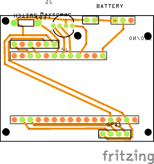
| Rendering in the most compact form. |
The test version I have created is single sided (for ease of wiring), has 8mm high sockets (to enable me to re-use the components) and still only measures 50mm x 70mm x 45mm. It also includes a 3.5mm mono headphone socket for a remote switch.
Please note: All the information here is for guidance only. If you're unsure of what you're doing, please get someone qualified to help (i.e. not me!). Most of the components are fairly benign (although if you accidentally connect a 3.3 volt LED to the 5v USB input, it'll blow the top off and hit you on the forehead...), but the battery stores a lot of energy and must be treated with utmost respect.
Remember, electronic components run on magic smoke - when the smoke is released, they won't work.
The list of components is as follows:
- Adafruit Feather 32u4 Data Logger [>]
- Ublox NEO-7M GPS [>]
- Maxbotis Maxsonar [>]
- SPDT PCB Slide Switch [>]
- SPST Push Button Momentary PCB switch. [>]
- RGB LED 3.3v [>]
- 500mAh LiPo battery (optional) [>]
- 50mm x 70mm Double sided prototype board [>]
- 3.5mm Mono headphone socket (optional) [>]
- Square pin header sockets (optional) [>]
- JST connector(s) (optional, but the one on the battery will be wrong) [>]
The headers (10) and the JST connectors (11) can be omitted if you're brave enough to solder the components directly to the peg board. The LiPo battery is optional if you're happy to power via the USB with a phone charger battery.
You will also need to beg, steal or borrow a soldering iron with a very small tip, a small amount of 0.2mm2 solid core insulated wire and a blob of Blu-Tack to stop the GPS module wobbling (it should really be screwed down).
This is quite a lot more expensive than planned, so since building this, I have acquired a few more ultrasonic rangefinders (and one infra-red one) for testing. All of them are much cheaper than the Maxbotix one and two of them have built in temperature compensation in serial mode, so may be better suited. The limitation is the Adafruit Feather board runs at 3v3, which rules out the 99p HC-SR04. I will write a sonar/board comparison post(s) as soon as time allows.
3D Modelling
 |
| Rendering with header sockets and pegboard. |
Even (especially?) if you have never used a 3D program before and have the merest hint of programming or scripting knowledge, give OpenSCAD a try. I have created 3d models of each of the components which I will also upload to Github.
The picture to the right shows my double-sided modelling but as it was my first attempt, I swapped to single sided as I started to solder up. I later learnt you're supposed to do all the wiring on the opposite side to the components. It would probably be neater than my efforts. The PCB image from the previous post shows how to wire it up if you're so inclined.
This is the end result. All I need now is a box, a way of mounting it and the remote switch.


Coding for Arduino
The open source/Free software & hardware community really is a gift that keeps on giving. Without all the contributions of so many, this project would not have been possible.Not only are the specifications of the Arduino hardware open source (which is why you can buy such cheap clones), the IDE (Integrated Development Environment) used to program the Arduino is also freely downloadable. It ships with a *huge* number of example 'sketches' - each and every new library has examples included.
'Proper' embedded programming is new to me. Although I do some embedded Linux, my bread & butter has been enterprise scale databases. This was going to be a whole new experience. From terabytes to less than 32Kb. Oh my!
Here's the Arduino coding 101: There are just two main parts to an Arduino sketch - the setup() function, which runs once when you power on and the loop() function which runs over and over again until you power off or make the code barf (even then it seems to detect this and restart itself). This makes simple stuff really simple. You want to flash an LED? OK, turn it on, delay 1 second, turn it off, delay 1 second, rinse & repeat:
// From the Blink example:
void loop() {
digitalWrite(13, HIGH); // turn the LED on (HIGH is the voltage level)
delay(1000); // wait for a second
digitalWrite(13, LOW); // turn the LED off by making the voltage LOW
delay(1000); // wait for a second
}
Great. Or not so great. While you're delay()-ing, nothing else happens. If your GPS is reporting a position change, you're not going to see it, if your want to ping the sonar - it's not going to happen.
A 'normal' computer handles all of this behind the scenes. As a programmer, if you want a process to not interrupt your user interface, you spawn it off into a different 'thread' that runs in the background - the operating system then 'schedules' all the threads for you. If you're really scaling, you can spawn it off to a whole new datacentre... Not on the Arduino. You have one loop.
Building a simple state machine
Vanilla Arduinos do not do threads (although guess what, there is a library or two for that!), but it does have a number of internal timers. You can obtain the number of milliseconds (or microseconds) since your program started. If you now define how frequently you'd like to turn the LED on or off, you can count the number of milliseconds that have passed then take an action. But while you're counting, you can do other things.//Pseudo code
void loop() {
now = millis(); //Get the number of milliseconds since program start
if (now - previousOnOff >= 1000) { // If one second has passed
if (ledState == LED_OFF) { // If the LED is OFF...
digitalWrite(13, HIGH); // then turn it ON
ledState = LED_ON; // and record the state
}
if (ledState == LED_ON) { // If the LED is ON...
digitalWrite(13, LOW); // then turn it OFF
ledState = LED_OFF; // and record the state
}
previousOnOff = now; //Save the time we last turned the LED on or off
}
//Here we can do other things
//. . .
//And even more things
//. . .
}
There is a surprising amount of functionality required that has to fit into just over 28kB. Looking through the code now, I have implemented the following:
GPS Read
Using the TinyGPS library, the location is read via serial, once per second. This is the default transmit rate for most GPS modules. The rate can be changed but the setup codes appear to be different for each version, so it went in the 'too hard' pile. Once per second works well, but the code is designed to cope with faster or slower updates.From the GPS data, in addition to longitude, latitude, heading and speed, we also get the (very precise) time, which we use for both logging and to create the name of the log file.
When we do not have a fix, the raw NMEA data is sent to the USB serial port for debugging. The red LED will remain lit until a fix is found (or subsequently lost), then flashes once per second.
Sonar Ping
With a little empirical research, I settled on a 'sonar heartbeat' of once every 200 milliseconds. This ensures even fast passes are caught but gives sufficient time for other functions to happen. Each 'ping' is derived from the median of 5 rapid pings to remove outliers, handled by the NewPing library. I have also written my first Arduino library for the two serial sonars which is partially API compatible with NewPing. This means it will only require changes to a couple of lines of code to switch between different sonar modules.If a near miss occurs (less than one metre), the blue LED will flash rapidly until we have 5 clear pings. This also gives an indication if the sonar is blocked or has barfed and can be used to check calibration.
Write to SD Card
Arduino has two libraries to support SD cards (SPI and SD) which take care of most of the heavy lifting. One minor limitation is the 8.3 file name format (MSDOS is still biting us on the bum), so I settled for YYMMDDHH.csv. If a file already exists, it will be appended. The data is written after each ping but only flushed once every two seconds to reduce battery consumption.On startup, the presence of the SD card is checked and the green LED flashed twice to confirm. When recording there will be one short flash per second. If a file open or write error occurs, then there will be two long flashes per second.
Flashing the LEDs
To provide an easier interpretation of status, I've used a RGB LED. I've implemented a design that splits each second into 8 segments allowing each state to be indicated by each LED without clashing. The patterns are easy to update and 'visual' in the code:const byte GPS_NO_FIX = B11111111; // Continuous
const byte GPS_HAVE_FIX = B00000100; // Once per second
const byte RECORD_ERROR = B11101110; // Long flash, twice per second
const byte RECORDING = B00000001; // Once per second
const byte TAGGING = B00010000; // Twice per second (in combination with RECORDING
const byte NEAR_MISS = B10101010; // Four times per second
const byte LOW_BATTERY = B01010101; // Four times per second OR'd with GPS_HAVE_FIX
These constants also serve as status values, saving a few essential bytes.
Single switch control
The push button implements a medium press for record on/off and a short press for tagging on/off. It could also implement a long press if required. A side effect of the implementation also deals with the 'debouncing' of the switch contacts. No, I'd never heard of it either!Battery State
This small but essential indicator was the final piece that I was able to squeeze in. On compile I now get the message:Sketch uses 28,096 bytes (97%) of program storage space. Maximum is 28,672 bytes.
It has taken some effort to trim the code to fit - so although quite functional, it is currently in need of a bit of tidying...
Next Steps
I'm currently learning/working on an Android OTG version, which will significantly reduce the cost of the primary parts. The phone will provide the GPS, logging and power, with the slight downside of a cable connection. Logging to the phone should also enable easier uploads of the data and may provide a basis for a Bluetooth version. However, this is incredibly distracting (read: time consuming) so have not yet started the Github learning curve...Part 4: The Arduino Code